The Roller Screw Computer Aided Design (CAD) is a digital product sandbox used to determine geometric parameters (dimensions, shape of the surface), accuracy parameters (positioning precision), indicators of physical and mechanical characteristics, and the life cycle of key components of precision roller screw units. A Product Data Management (PDM) system is the DT of a product at the stage of its development and customization. Roller screw CAD significantly reduced the time of development and customization of the product. In particular, roller screw CAD has accelerated the development of new basic unified module roller screw gears. In addition, roller screw CAD allows virtual testing, thereby reducing the time to market.
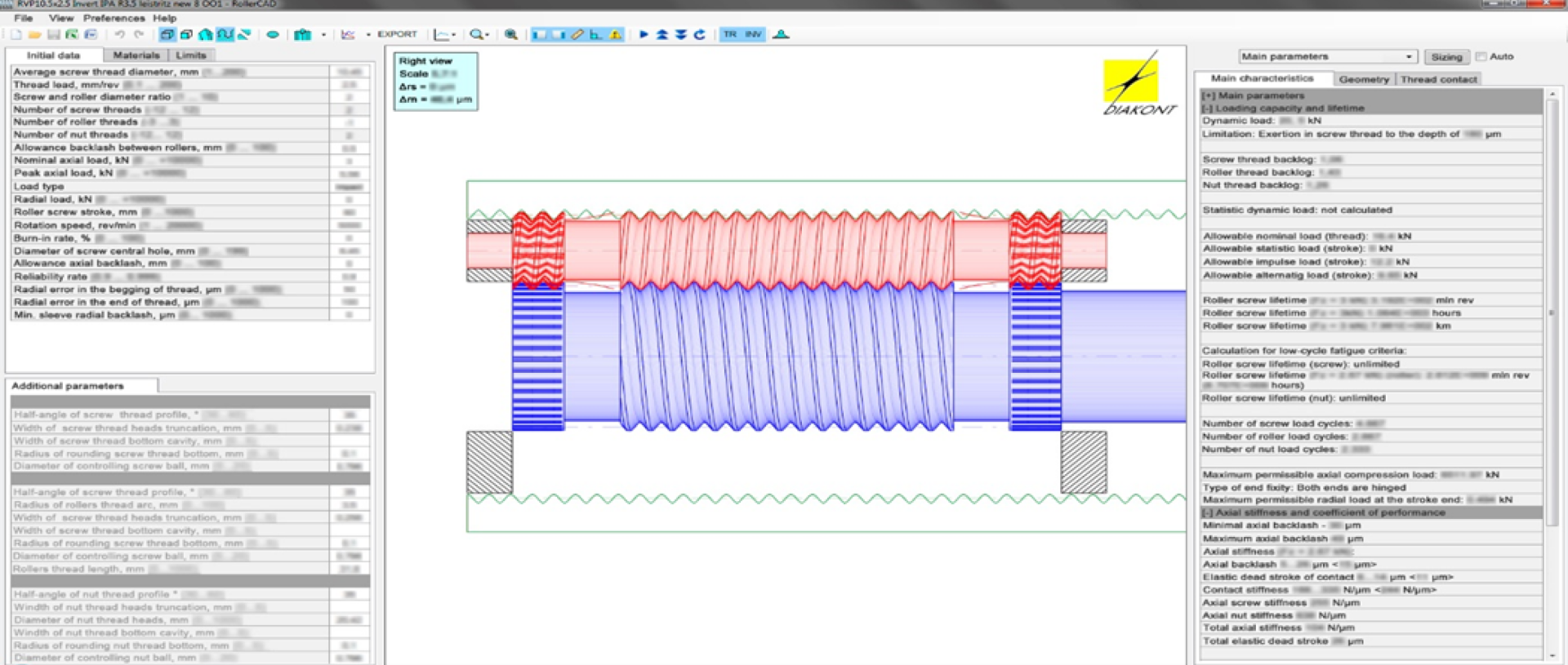
Diakont roller-screw CAD design software interface
In addition to the digital sandbox, a real test site was created, including a production site, testing, and measuring base. The feedback obtained from a real test site was used to improve the relevant algorithms. The roller screw CAD is not just a separate tool, but an essential Digital Tool integrated into the company infrastructure, and a novel component of the hyperautomation framework. In this case, changes in the design parameters of the roller screw, will cause respective changes in the design of the actuators, in the process and technology, and finally in production costs, and that goes automatically. Developing and planning of the launch of new product into production is supported by an estimation of all the changes needed withing the production system and their influence on the economic parameters of the entire business at every stage.

(Proprietary CAD-FEA displayed)
“We use proprietary CAD software to design roller screw. It includes finite element analysis to show that
CAD of the production process is a set of DTs for different processing methods used for product development. Depending on the design parameters, such as overall dimensions, manufacturing accuracy, and the number of processed surfaces, the CAD of the production process provides an estimate of the main technological parameters, such as processing, preparatory/final/auxiliary times, and complexity of operations. Process CAD contains a parameterized database of primary production and automation equipment and allows for a quick assessment of the new parameters of the technology if the equipment is changed. The main objective of this step is to develop a process that provides cost optimization, reduces the length of production cycles, ensures the stability and flexibility of the production process, and minimizes dependence on human mistakes. This step also defines the methods and tools for automating the main and auxiliary operations of the production cycle, such as storage, transportation, machining, assembly, testing, measurement, and control and management processes.
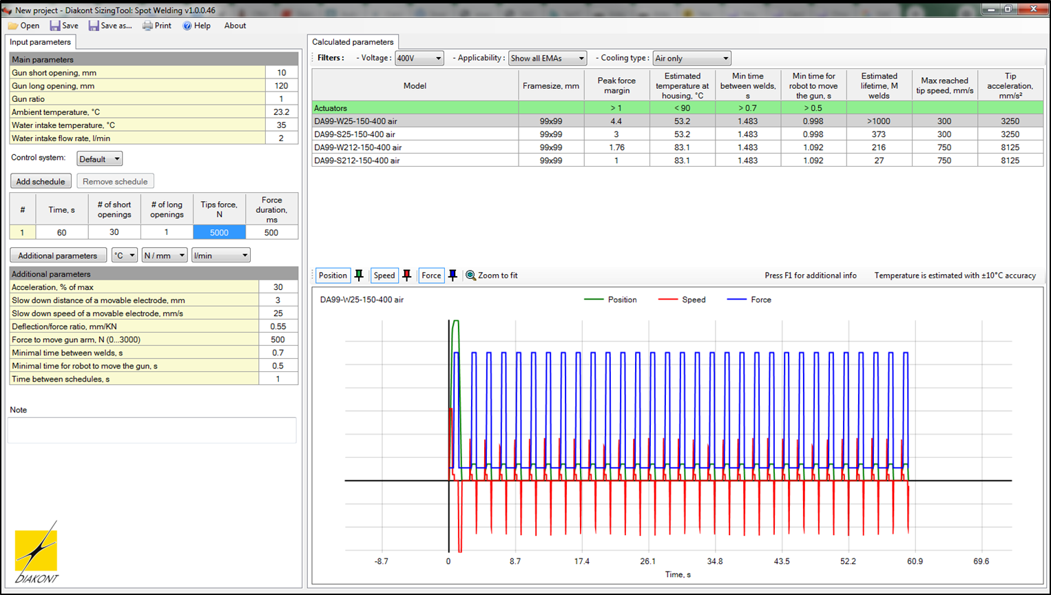
For the convenience of customers Diakont has developed a Sizing Tool – software which calculates actuators performance at designated weld cycle parameters. It is possible to see which actuator models fit the requirements of the specific welding cycle,